Tangentially, we can fix your raycaster.
Raycasters are a nifty way to approximate a 3D scene, but care must be taken to avoid introducing distortions that can spoil the effect.
So you’ve written a raycaster. You’ve sorted out the issue where right and left were mirrored, it no longer crashes randomly due to integer overflows when you get too close to certain walls, and it reliably exceeds mid-single-digit frame rates. Congratulations! I bet you feel a real sense of accomplishment in getting this far.
But something’s not right. The walls don’t look like you remember them looking in Wolfenstein 3D. They’re bent, stretched, distorted… There’s something not quite right about them. You can’t exactly articulate what the problem is, and no idea where to start trying to fix it on your own.
So you turn to web searches, digging up forum threads and Stack Overflow posts. Their problems are sort of like yours, but their code is pretty different. The answers are obtuse, terse, or condescending—somehow insinuating that the asker should know better while at the same time accusing them of not knowing anything in the first place. The fact is, most people who have walked this path have encountered problems like this. Some knew how to fix it intuitively, some never fixed it and eventually lost interest in the project. Since you found this article and have read this far into it, I’m going to try my best to explain what’s going on so you can be better equipped to get through it and onto doing something more fun. This is not going to be a quick in-and-out kind of affair—we’re going to go into deep detail and that’s going to take a bit of time. I promise to try to make it pleasant, and hopefully you will find it was time well spent.
The fact is, you might be experiencing two problems at the same time. They have different underlying causes and different solutions, but they combine together into the same kind of visual weirdness.
This is my raycaster. There are many like it, but this one is mine.
This is not an article about how raycasters work or what’s involved in writing one. You already have one and it doesn’t work right. The purpose of this section is to make sure you’re using the same terminology I am, and as a quick double-check that you didn’t pick up any incorrect information from somebody who was going for a “Quantity Over Quality” badge on Discord.
To raycast a scene, you need a viewer standing on a point in two-dimensional space represented by a pair of X, Y coordinates. This viewer is turned toward some face direction, an angle This article uses degrees to express angles, but you can use whatever you want as long as you’re consistent. which corresponds to the center of the rendered scene on the screen. The viewer has a field of view (FOV) which governs how much of the scene can be seen to the left and right of the face direction. For a FOV of 90° (which is not unusual) an object centered at the leftmost edge of the screen is 45° left of the viewer’s face direction, and an object at the rightmost edge is 45° right of the face direction. The viewer’s X, Y, and face direction are compared with a map of grid squares, some of which are empty and others full. An empty square is space that can be seen past and walked through, while a full square is an obstruction that represents something solid like a wall.
For each vertical column of screen pixels that needs to be drawn, a ray is emitted from the viewer’s position, at an angle influenced by the face direction and relative angle within the FOV, and checked against the map grid contents. When something solid is hit by that ray, the distance between the viewer and the hit position is computed, and the reciprocal of this distance is (eventually) the height of the pixel column that is drawn on the screen.
There are numerous ways to advance the rays, check for intersections, calculate distance, and do all of the internal bookkeeping and precomputation to make it run efficiently on the target hardware. So we’re not going to get much more specific into any one implementation than we have here.
A pair of coordinates is a pair of coordinates, right?
Sometimes you’ll hear people claim the cause of all the problems is the combination of rectangular and polar coordinate systems. There’s a bit of truth in that, but the reality is more nuanced. The rectangular and polar coordinates are the murder weapons, but they’re not the crime.
In 2D rectangular coordinates, we use an X coordinate to express the horizontal position of an object relative to an origin axis, while the Y coordinate does the same thing in the vertical direction. This is a two-dimensional extension of the one-dimensional number line that I’m sure somebody taught you at some point during your elementary school education.
Polar coordinates consist of an angle called θ (“theta”) and length called r (“radius”). Combined, these two values locate a point by following this process: Starting from a origin pole and zero angle, turn to the angle θ then move r units in that direction. That’s the point that the coordinates refer to.
It’s possible to convert from polar to rectangular coordinates with no loss in accuracy, aside from possible rounding errors involved in the calculation:
$$ \begin{aligned} x &= r \cos \theta \\ y &= r \sin \theta \end{aligned} $$And just as easily from rectangular to polar:
$ \textrm{atan2}(y, x) $ is essentially the same as $ \arctan {y \over x} $. Both of them convert the rise-over-run slope of a line into the equivalent angle. The difference is that atan2 can see the sign of both values and can use that information to determine which quadrant the angle is in. The regular arctangent only sees the sign after the division has occurred, and may produce a result that’s flipped 180° from what might be expected. $$ \begin{aligned} \theta &= \textrm{atan2}(y, x)\\ r &= \sqrt{x^2 + y^2} \end{aligned} $$
There’s a pretty good chance your raycaster already has some if not all of these conversions in it somewhere already. The map grid and viewer position are all rectangular, while the ray angles and distances are all polar. Converting between these systems is the basis for how the whole thing works in the first place.
Remedial geometry
You may already know this, so feel free to skip it. But we’re going to need the diagram at some point, and I’d rather get that out of the way upfront.
The memory aid for the three core trigonometric functions is soh cah toa. Expanded, it means this:
- The sine of the angle θ is the length of the opposite side divided by the length of the hypotenuse.
- The cosine of the angle θ is the length of the adjacent side divided by the length of the hypotenuse.
- The tangent of the angle θ is the length of the opposite side divided by the length of the adjacent side.
All those words are talking about a triangle, specifically a right triangle. In a right triangle, one of the angles is locked to 90° and cannot change. One of the other two angles is called θ, and the final angle is anonymous and just goes along for the ride. In any triangle, all angles must sum to 180°. There’s no way to change one angle without causing a different angle to change, preserving this 180° sum at all times. Since a right triangle must contain a 90° angle, the anonymous angle becomes whatever part of the remaining 90° that θ didn’t take. The “straight lines” that make up the triangle’s outer shape are called sides, and the one farthest from θ is called the opposite side. The hypotenuse is the side farthest from the right angle, and is always the longest side of the three. The adjacent side is the remaining side that touches θ.
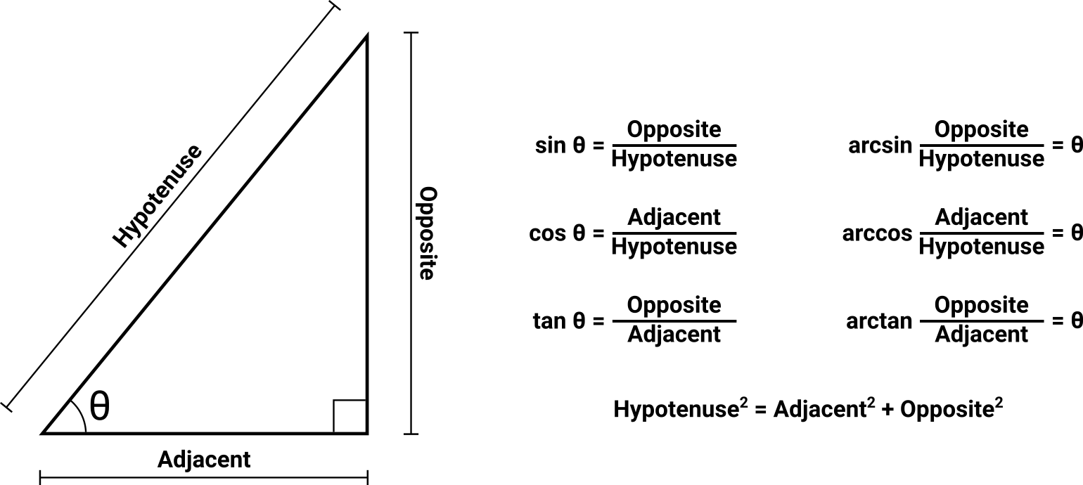
Cheat sheet showing the sides and relevant angles of a right triangle, along with the core trigonometric equations that express the relationships between them.
The trigonometric functions’ purpose boils down to either:
- I know two sides, and need to find θ.
- I know one side and θ, and need to find another side.
Sometimes you’ll find yourself in the position of having the inverse of one of these questions, in which case you’ll need the arcsine, arccosine, or arctangent. Despite the intimidating names, all they do is invert the operation of the corresponding function. Sine turns an angle into a length ratio, and arcsine turns that length ratio back into the angle. Not scary at all.
If you find yourself asking a different question, you probably need to use a different function:
- I have two angles and need to find the third angle. (Use subtraction.)
- I have two sides and need to find the third side. (Use the Pythagorean theorem.)
- I have less and need more. (Use ibuprofen.)
You can do some very useful things by placing θ onto a rectangular graph at position 0, 0. It might be fun to take another look at the rectangular/polar conversion formulas while you do that!
Through the eyes of a fish
The first rendering distortion problem is usually the most obvious to the casual observer: When facing a wall head-on, the expectation is that the wall should be the same height across the entire screen. But it’s not. Expressed a little more academically, the adversarial case is one where the face direction is perpendicular to a wall, with the viewer having sufficient distance from that wall to see its top and/or bottom edges. The problem manifests itself as the wall appearing taller in the center of the screen, and progressively shorter at the screen edges. This is colloquially referred to as a “fish eye” or “fish bowl” distortion.
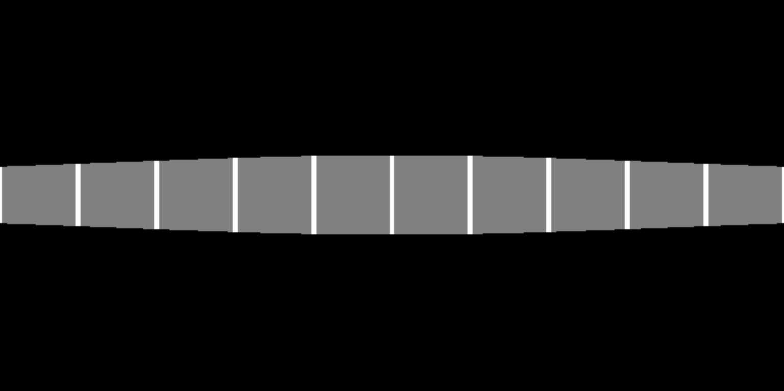
Rendering of a wall perpendicular to and approximately five map units away from the viewer, exhibiting fish eye distortion.
The walls in this view are not actually getting shorter at the screen edges; they are getting farther away. Simply put, the raycaster is correctly rendering the height of a pixel column based on a distance value that is not correct. We can’t fix the height because the height is not what’s broken here.
Let’s take another look at the top-down view of this scene. We’ll define the viewer as having a 90° FOV and a distance five units away from the wall. The face direction is perpendicular to the wall. All other parameters and markings are irrelevant and omitted.
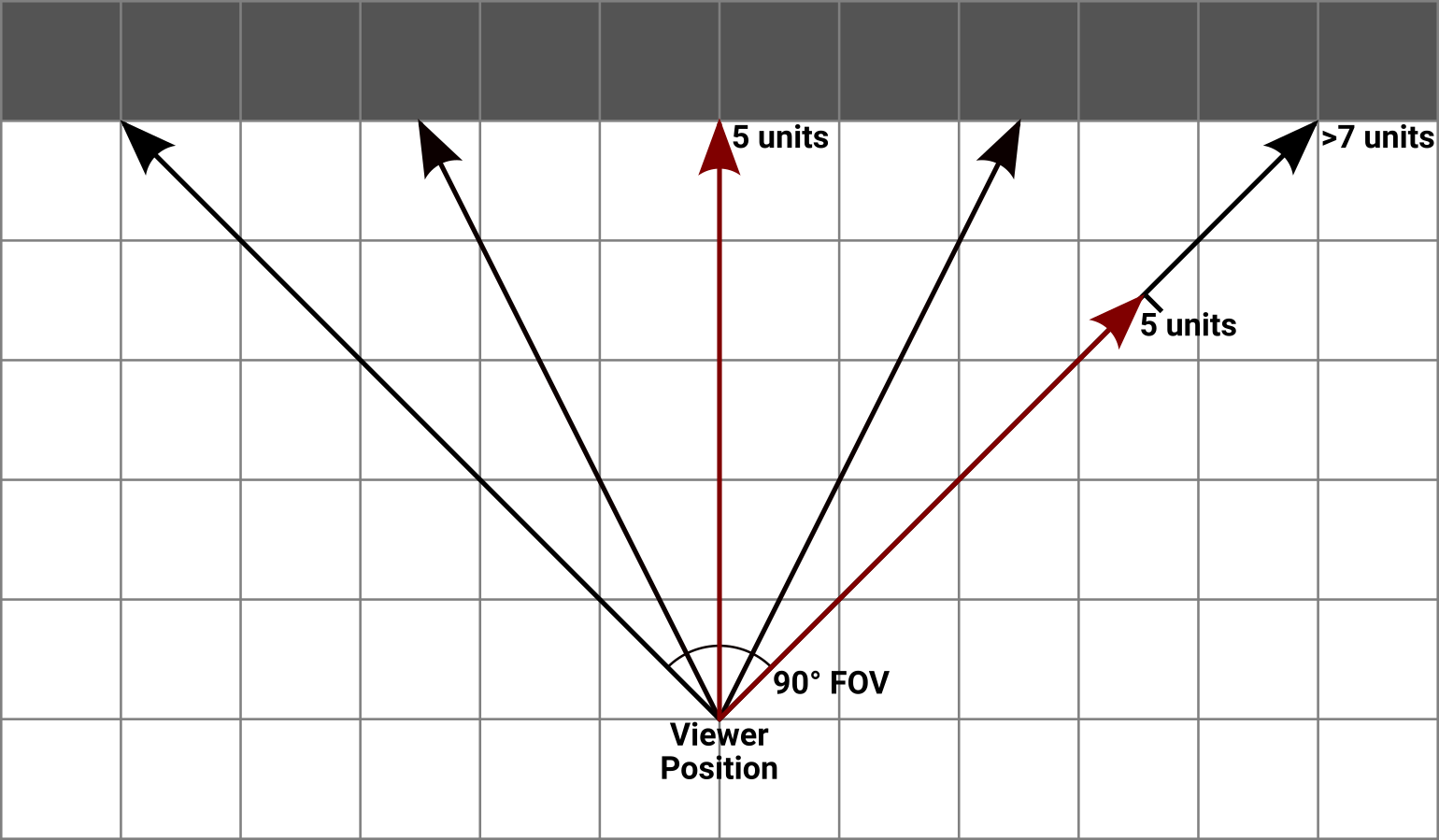
Top-down view of a scene exhibiting fish eye distortion. The center ray travels five units to reach the wall, while the rays at each edge of the FOV travel more than seven units. The rightmost ray is marked with a copy of the center ray to show where the wall would need to be hit to render as a straight line.
The ray at the center of the FOV is five units from the wall. The rays at the far ends, however, are considerably longer than that—they are more like seven units long. Because these rays are leaving at an angle relative to the center of the view, they have to travel farther before they hit something. This difference in travel distance between the center ray and the edge rays is what causes the problem. And actually, it’s only a problem because your screen is flat. If you rendered the scene this way onto a large screen with a sufficient curve and stuck your head close enough that it covered most of your own real-life field of view, the effect would look more or less correct to your peripheral vision. But we don’t have gigantic curved monitors a foot from our faces. Or at least I don’t.
So what do we really want here? In order to draw the wall straight, it’s necessary to make all of the rays stop at the distance that the center ray travels: five units. To do that, our map would need a curved concave surface instead of a straight wall. How the heck are we going to do that?
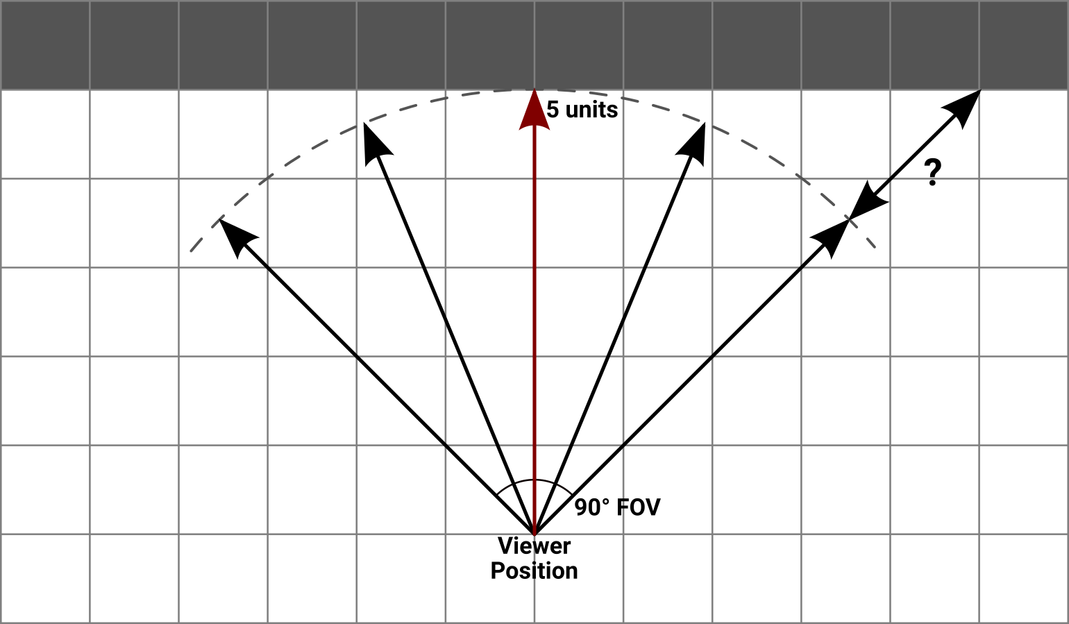
Top-down view of the same scene marked with the outline of an arc where we need the wall to appear to be.
We’re not. We’re going to keep doing what we’re doing, but see if there’s a more direct way to replicate the problem. Let’s take a look at what we know:
- Measured conventionally, the viewer is five units from the wall.
- The viewer’s face direction is perpendicular to the wall, and the ray that corresponds to this position travels the correct distance. When rendered, this ray produces a wall of the desired height.
- The total FOV is 90°, which can also be thought of as two mirror-image half fields—one 45° less than the face direction at one edge of the screen and 45° more than the face direction at the other edge. The rays corresponding to each of these end angles has a distance value that is too high, producing a wall that looks too short.
For each ray in the scene, we know the cast angle that was followed as it traveled through the map. We also know the viewer’s face direction because we directly control it. The difference between these two angles can be used as a θ value for a right triangle. Because the face direction is perpendicular to the wall, it makes sense to use the wall as the triangle’s opposite side, the distance from the wall as the adjacent side, and the distance traveled by the ray as the hypotenuse.
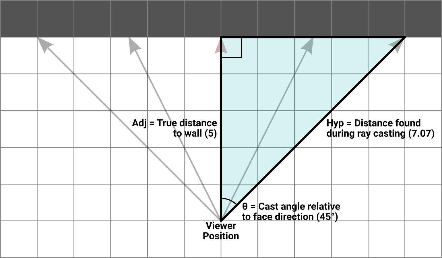
Top-down view of the same scene with a right triangle overlaid on half of the FOV. θ is the difference between the viewer’s face direction and the cast angle for the rightmost ray, the adjacent side is the true distance away from the wall, and the hypotenuse is the distance traveled by the ray that followed this cast angle. The other half of the FOV is symmetrical and works the same way.
With the values we know for certain, the best fit is the cosine function. Stated directly:
$$ \cos(\theta_{cast} - \theta_{face}) = { D_{true} \over D_{ray} } $$When the face direction and the cast angle are the same (that is, when casting the ray for the center of the screen) the θ difference is zero and its cosine is one. Therefore the two distances are equal and the ratio of distances is also one. Elsewhere, at the screen edges, the difference in θ is ±45° which produces a cosine result of about 0.707. This corresponds to a ratio where the distance traveled by the ray is larger than the true distance to the wall. With a single trigonometric function, we’ve modeled our problem.
Let’s keep the model, but throw out the original question. Now suppose the viewer is standing at an arbitrary place in the map, facing toward an arbitrary direction. They are no longer looking perpendicularly at a wall. In fact, nothing in the view is perpendicular to anything. As we cast rays through this scene, we still know the face direction and the cast angle, and we still know the distance values that are coming back from each ray. But we don’t know how far away we are from that ideal perpendicular spot, if a reasonable one even exists.
Let’s plug our numbers in anyway:
$$ \cos(\theta_{cast} - \theta_{face}) = { \textrm{?} \over D_{ray} } $$Turns out we know more than we think we do. Applying a bit of algebra:
$$ D_{ray} \times \cos(\theta_{cast} - \theta_{face}) = \textrm{?} $$That’s perfectly solvable. And as it turns out, the unknown value ends up being the distance that we originally wanted to get, in which there are no adjustments at the center of the viewer’s screen, but progressively shortened distances as the cast angle moves away from the center. It’s not even a kludge or a hack; this is a mathematically pure way to convert the hypotenuse that the ray distance gives us into the adjacent distance we actually want.
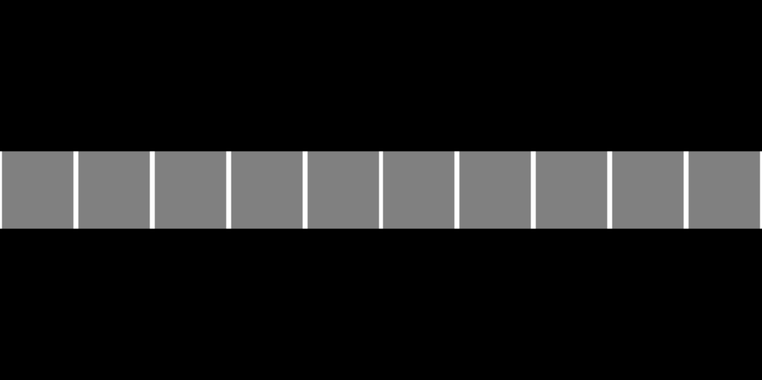
Rendering of a wall perpendicular to and approximately five map units away from the viewer, with the fish eye distortion corrected by adjusting ray distance values.
TL;DR: To correct fish eye distortion, multiply each ray’s travel distance by the cosine of the difference between that ray’s cast angle and the viewer’s face direction.
Getting all bunched up around the edges
Now that the walls are straight, everything is peachy. You walk through your little maze of boxes, turn some corners, and… Something still seems off here. You walk to a long hallway You made a long hallway, right? and sight down one of the walls. It’s still not straight. This time they grow in height at the extreme left and right screen edges.
You walk to a doorway and let your eye pan across the screen as you hold one of the “turn” keys. Not only to the walls get higher at the screen edge, they get narrower too. Things look alright at the center of the screen, but stretch and morph in both height and width as you turn. It gets a little better with a reduced FOV.
Back on the forums, some people suggest that there’s no way to get a 90° FOV without having some amount of this type of distortion. That feels like a cop out. There’s gotta be a way to figure out the reason for this.
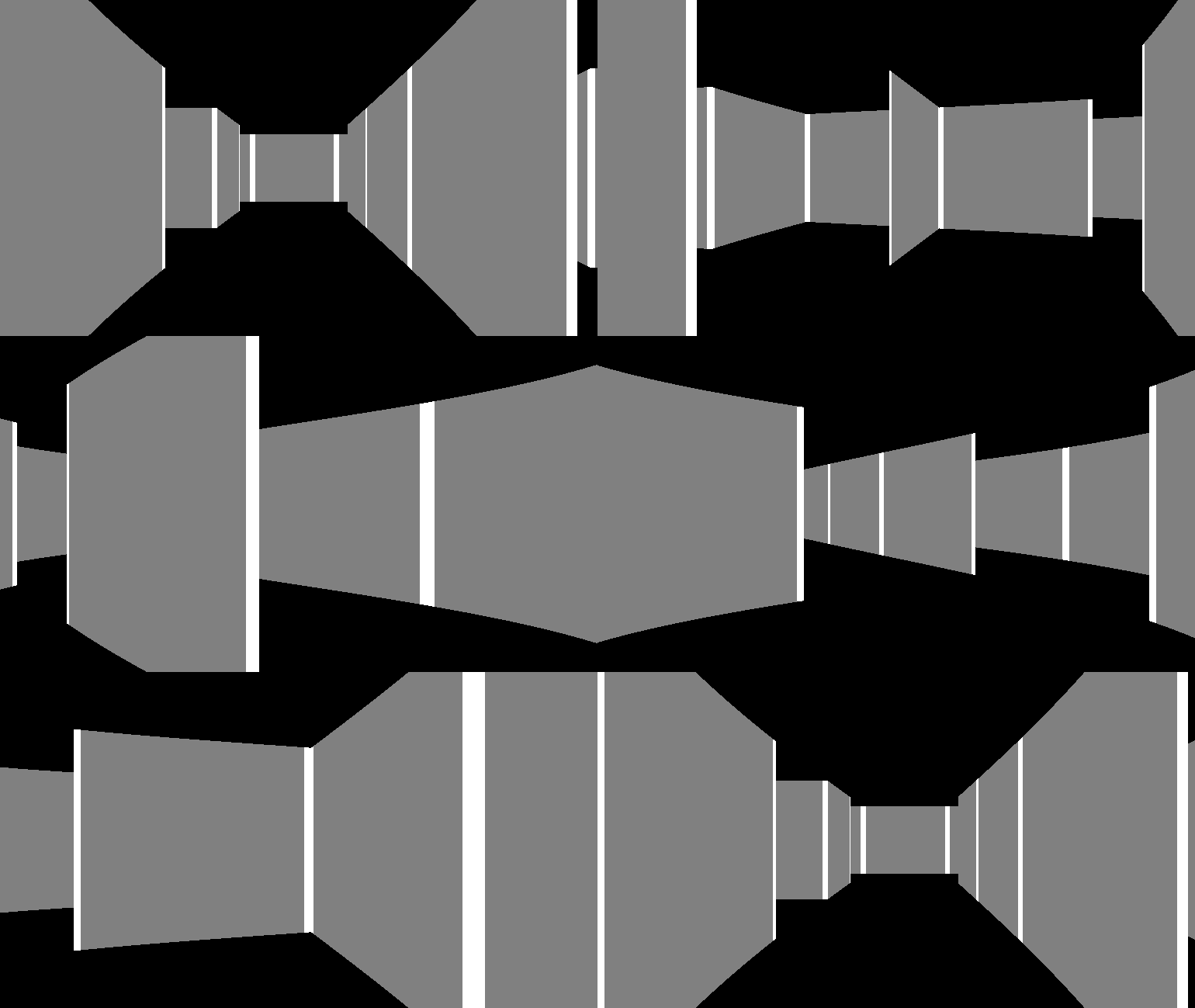
Animated loop of a 360° turn showing the scene rendered with incorrect ray spacing.
The distances to all of these walls is correct (we made sure of that in the previous section). The height calculation and rendering are both correct. Mostly correct. Read through to the end of the article. What’s wrong here is that the cast angle chosen for each ray is subtly wrong for its position on the screen. And when I say subtle, I mean subtle—this problem isn’t nearly as overt as the fish eye was, but its cause cuts deep into the art and science of rendering.
The outermost loop of any raycaster iterates over n screen columns, casting out n rays. The FOV angle between the first and last ray is a fixed constant, so it’s only logical to divide the FOV angle by n and use that step value to increment the ray angles as the screen is drawn. That’s the correct thing to do at the center of the screen. It’s also the right thing to do at the extreme edges of the screen. All those other columns in between, though? They’re all wrong. When you cast a set of rays out from a point using this scheme of fixed angular distance between each, you’re doing something like this:
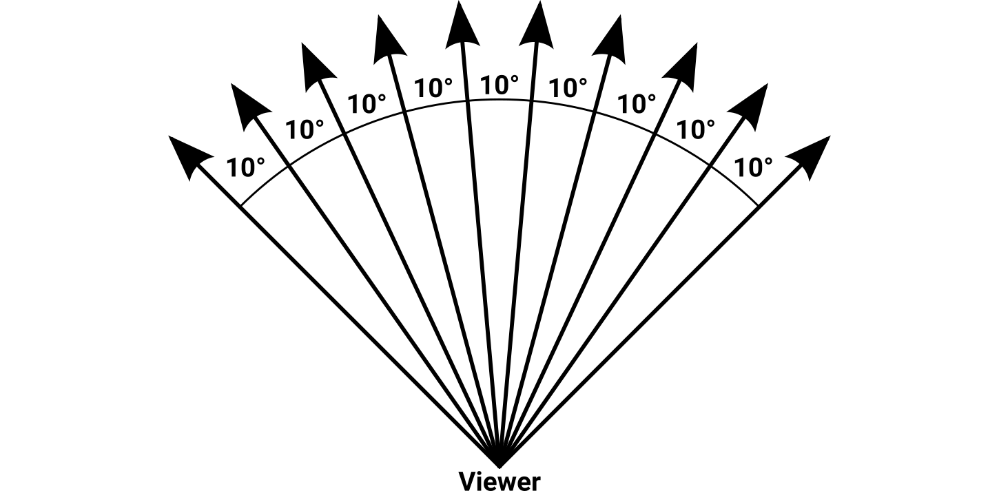
Top-down view of several rays leaving a point representing the viewer. Each ray has a fixed angular distance of 10° from its neighbor, for a total FOV of 90°.
The viewer is that point. The funny thing about a point is that it is a point—it has no height or width, no area or volume, no ambitions or dreams. It is smaller than a millimeter, smaller than a pixel, smaller than a floating-point ulp, smaller than the quarks and leptons that bind this bizarre universe together. When two or more rays converge at a point, there is no meaningful way to measure a distance between them. The ray from the left edge is in the same place as the ray from the right edge, which is in the same place as every other ray in the scene. There is no way to determine where each ray should appear on the screen because all of the rays have commingled into something immeasurably small.
This phenomenon happens in cameras and our own eyes. The light from a scene enters an optical lens and is focused down to a very small area called the focal point. The beams of light all cross each other and continue on a bit farther before reaching the light receptor, whether that is an image sensor or our retinas. This crossing actually produces an image that is upside-down relative to the real world, but cameras and eyeballs are wired to interpret that as being the right-side-up way of looking at it.
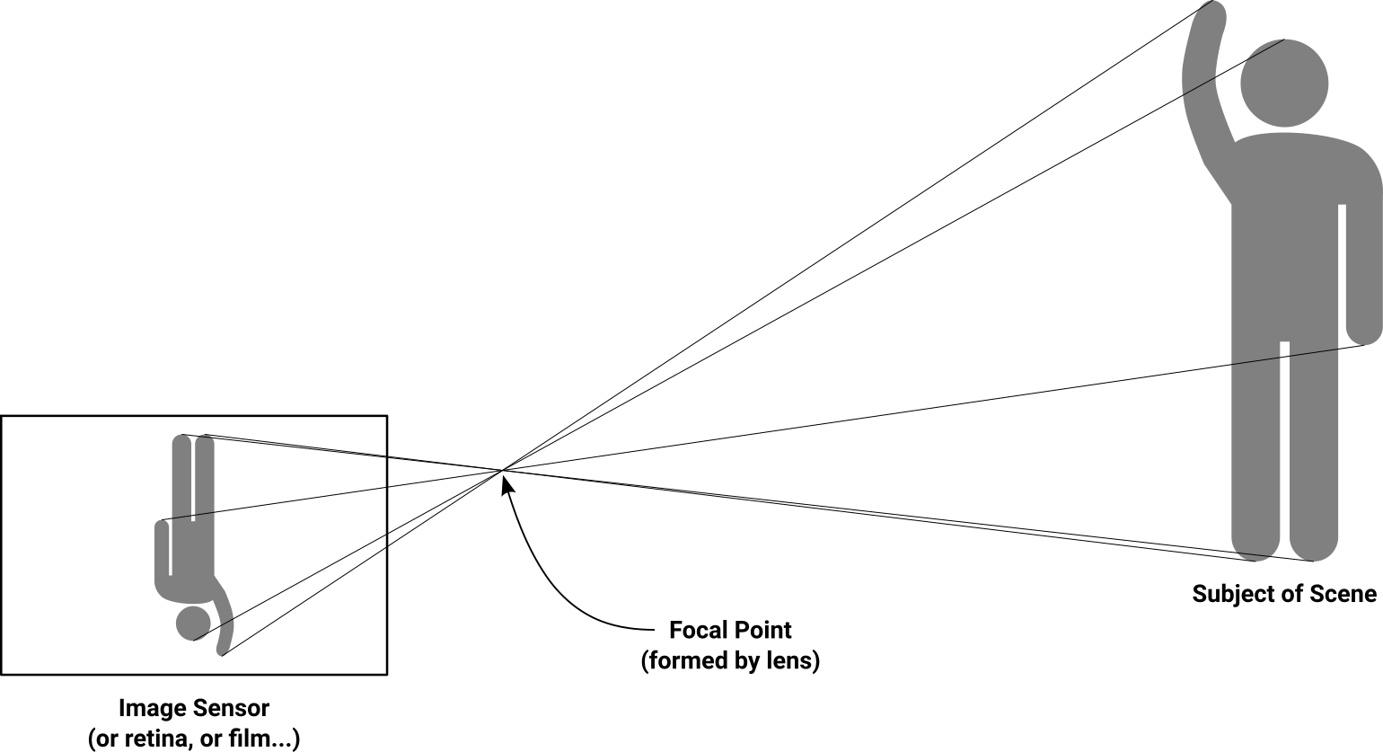
A quick sketch of what happens—broadly—behind an optical lens in cameras and eyes. The lens “collects” the incoming rays of light so they all converge at a single focal point, and the image is reproduced on a flat surface some distance behind that point.
The closer the receptor is to the focal point where the light beams cross, the more difficult it is to resolve the details between those beams. When the receptor is placed right at that convergence point, all it sees is a single searingly bright point with no details or distinguishing features whatsoever.
We’re building a raycaster here, not an ant-burning magnifying glass apparatus, and we unwittingly turned the screen into a projection plane. A mathematically flawed projection plane, but a projection plane nonetheless. When we decided that the left edge of the FOV mapped to the left edge of the screen, and ditto for the right, we did this:
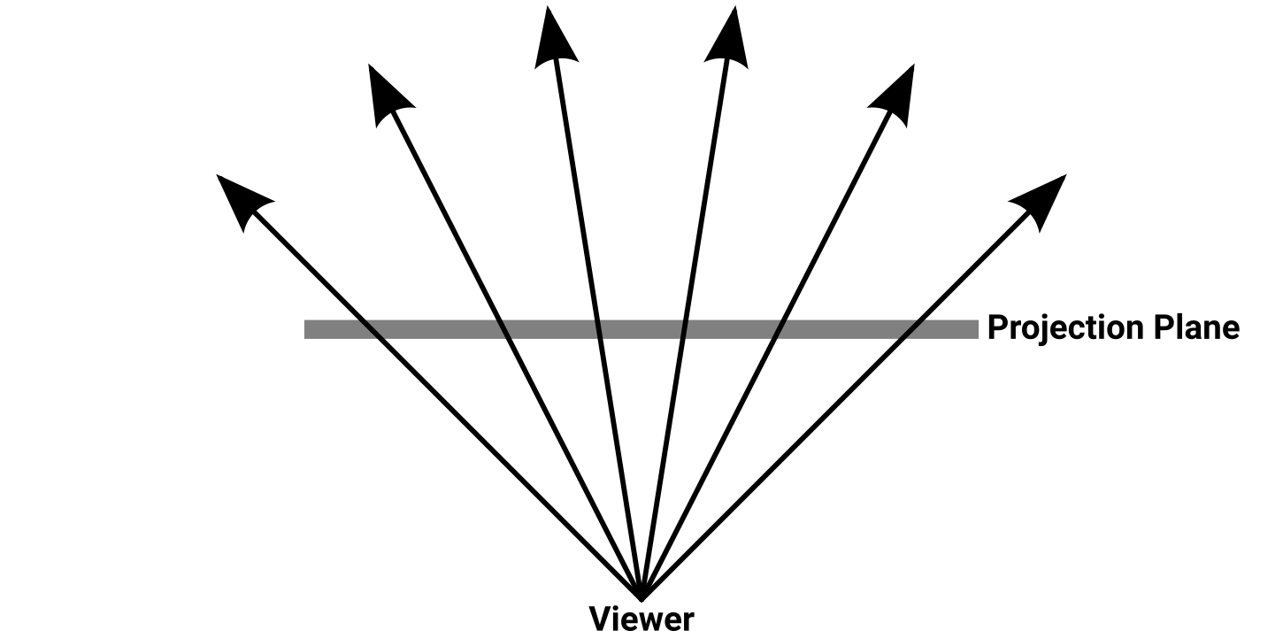
Top-down view of several rays cast from the viewer’s position through a projection plane. The plane does not have a well-defined size or distance from the viewer; it is defined only in terms of the angular distances between the rays that pass through it.
Rather than putting the plane behind the focal point (which would produce a flipped image like a camera does) our projection plane is in between the focal point and the subject. The projection plane is like a tiny copy of the screen, and anything that happens on this plane also happens proportionally on the screen. Now, how far away from the viewer position is the plane? How wide is it in terms of map units? We didn’t specify, and it turns out that it doesn’t matter. As you slide it farther away from the viewer position it gets bigger, but the rays get farther apart too, so everything stays proportionally the same when it’s scaled to the screen’s dimensions.
The rays are evenly spread out, so it makes natural sense to divide this plane into evenly spaced columns, each one corresponding to a column of pixels on the screen. The math is so elegant, surely it must be right.
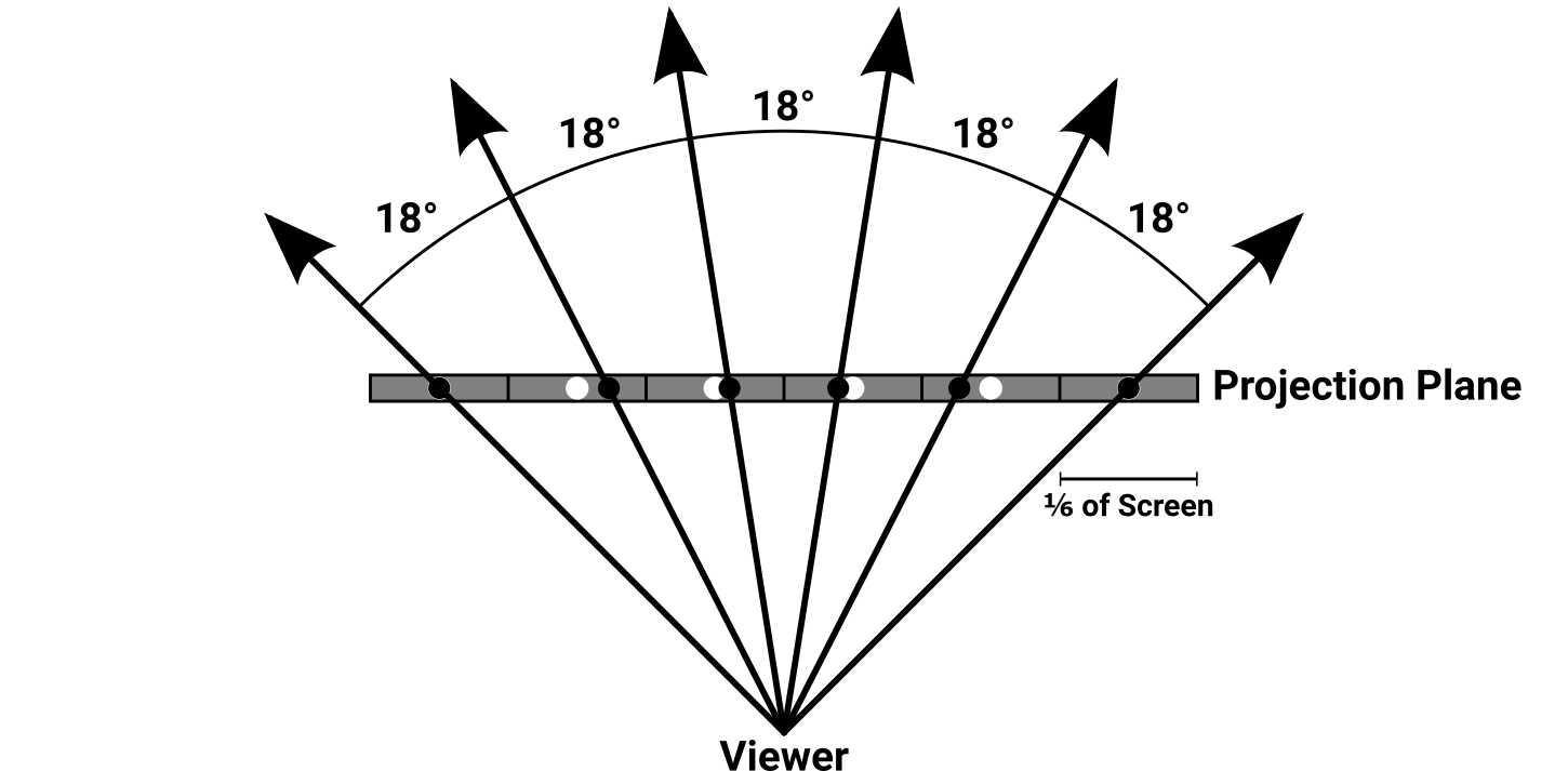
Top-down view of six evenly-spaced rays intersecting six equally-sized cells of a projection plane, covering a 90° FOV. A real raycaster would have hundreds of rays, but the magnitude of the error seen at the individual rays would be similar to what is pictured here.
In the above image, the plane is divided up into evenly sized cells with unfilled circles at their centers. As each ray passes through the plane, a solid dot is placed along the ray at the location where it passes through the plane. Notice anything wrong with the circles and dots? Even though the end rays pass through their intended circles perfectly, the inner rays do not. What’s more, the error between the circles and dots varies considerably depending on the position along the projection plane.
Of course, your raycaster undoubtedly draws hundreds—if not thousands—of rays on the screen. This image only shows six, but the relative error seen on any single ray in this image would be comparable to the error found in any scene using this kind of ray spacing. If you imagine a projection plane with hundreds of cells, it’s quite apparent that these dots would end up in completely wrong cells.
In short, we can’t use linear spacing for pixels on the projection plane or screen (both rectangular systems) while simultaneously using linear spacing for the angular distance between the rays (a polar system). One has to be modified to accommodate the other. And since it would be pretty hard to adjust the spacing of the pixel columns built into your screen, the only thing we can reasonably do is adjust the spacing between the rays. But how are we going to even begin doing that?
Now you’re just projecting
Those forum guys are still at it, with some of them suggesting that the only way to fix this correctly is to start expressing everything as a vector and then do matrix operations on those. That doesn’t really sound like much fun, and I would argue it does a disservice to people who may not be as far along in their math education. I know that when I tried working on my very first raycaster in high school, I had no real understanding of matrix math or how to intuitively apply it in different situations. Hell, I still don’t have an intuitive understanding of matrix math or how to apply it most of the time. Sure, you could use vectors and matrices to fix this, but you don’t need to if you don’t want to.
The good news is that most of your hard-won raycasting code doesn’t need to change. The meat of this fix is to alter the way the cast angle is chosen for each ray.
Suppose we bumped our FOV angle up to 100° to really aggravate the distortion. We still have a projection plane that covers this entire viewing area, but we now need to specify exactly how far away it is from the viewer’s position. It doesn’t actually matter what this distance is, but it must be something. For clarity and absurdity, I am going to choose six map units. I don’t know anything about your particular raycaster, angle measurement system, screen resolution, or what the scale of your map units is, yet I pretty much guarantee that a projection plane distance of six units would work in your raycaster. Even if the chosen distance results in the projection plane being located on the far side of a wall relative to the viewer, all the math will still work properly.
With the FOV and projection plane distance, we can use trigonometry to figure out the plane’s fixed parameters. One particularly significant hurdle is that we don’t have any right triangles to work with. What we’ll need to do is cut the FOV in half, producing two right triangles that are mirror images of each other. It takes a bit of mental energy to remember that sometimes you’re working with half the screen, half of the FOV angle, and half of the projection plane, but you get used to it after a while.
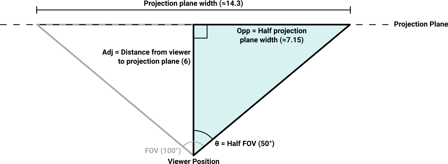
Construction of a projection plane using the viewer’s FOV and distance values to calculate the overall width. To permit the use of right triangles, the FOV is split into two mirror-image halves, each forming a right angle with the projection plane.
Algebra ensues, and we are able to determine (based on $ D_{projplane} = 6 $):
$$ \begin{aligned} {W_{projplane} \over 2} &= D_{projplane} \times \tan\left({FOV \over 2}\right) \\ \\ W_{projplane} &= 6 \times \tan\left({100^\circ \over 2}\right) \times 2 \\ \\ W_{projplane} &\approx 14.3 \end{aligned} $$It’s only necessary to calculate this projection plane width ($ W_{projplane} $) once at the start of your program, unless your FOV changes dynamically (in which case you’ll need to recompute it each time that happens).
The screen pixels and projection plane coordinates are linearly related, which makes conversion between the two a straightforward matter of multiplication or division. So, if your rendered screen was 1,440 pixels wide, each screen pixel would be represented by about 0.01 units on this demonstration projection plane. As the rendering loop iterates over the columns of screen pixels, the corresponding X values on the projection plane need to be computed. We might as well rip that bandage off right here and now:
$$ \begin{aligned} X_{max} &= W_{screen} - 1 \\ \\ X_{projplane} &= {(X_{screen} \times 2) - X_{max} \over X_{max}} \times {W_{projplane} \over 2} \end{aligned} $$There’s no trigonometry in there, just linear scaling stuff. The essence of what it does gets a little buried, though. Given a screen width in pixels $ (W_{screen}) $, In most programming languages, the column numbering goes from zero to $ W_{screen} - 1 $, and the use of this corrected $ X_{max} $ value avoids a fencepost error. and an X position on that screen $ (X_{screen}) $, this calculates the equivalent X position on the projection plane $ (X_{projplane}) $. The left side of the equation normalizes the X position on the screen to a range between -1.0 and 1.0 inclusive. This is multiplied by half of the projection plane width to calculate the corresponding $ X_{projplane} $ position. You can remove a redundant multiplication and division by storing “projection plane half width” instead of the full width. Once you understand what’s going on here, you can remove lots of redundant stuff. (For example, what happens later if the projection plane distance is set to 1?) (Recall that the projection plane is split into two halves with the zero coordinate situated at its center.)
Having turned the screen coordinate into an equivalent projection plane coordinate, we have located the point that this ray needs to pass through to accurately service this screen column, but we have not yet turned that information into a proper cast angle. It turns out that, knowing what we now know, that calculation is straightforward:
$$ \theta_{cast} = \textrm{atan2}(X_{projplane}, D_{projplane}) + \theta_{face} $$The cast angle can then be passed to the existing raycasting code without any further modifications. With this change in place, the ray spacing looks a little distorted from the top-down perspective, but the result on the screen is exactly what we want.
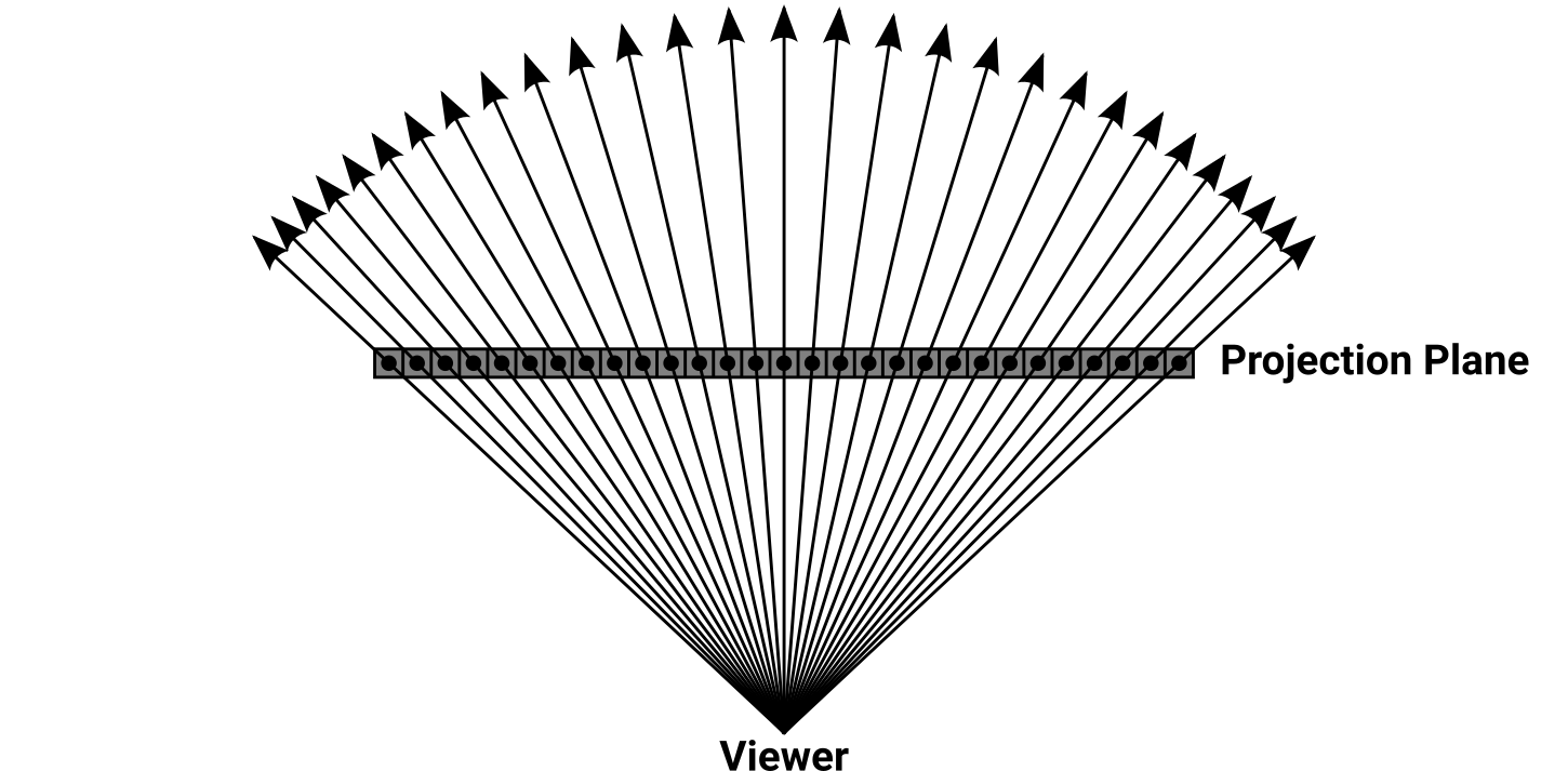
Top-down view of correct ray spacing through the projection plane. Each ray angle is uniquely determined using the arctangent of an X position on the projection plane divided by the plane’s distance from the viewer.
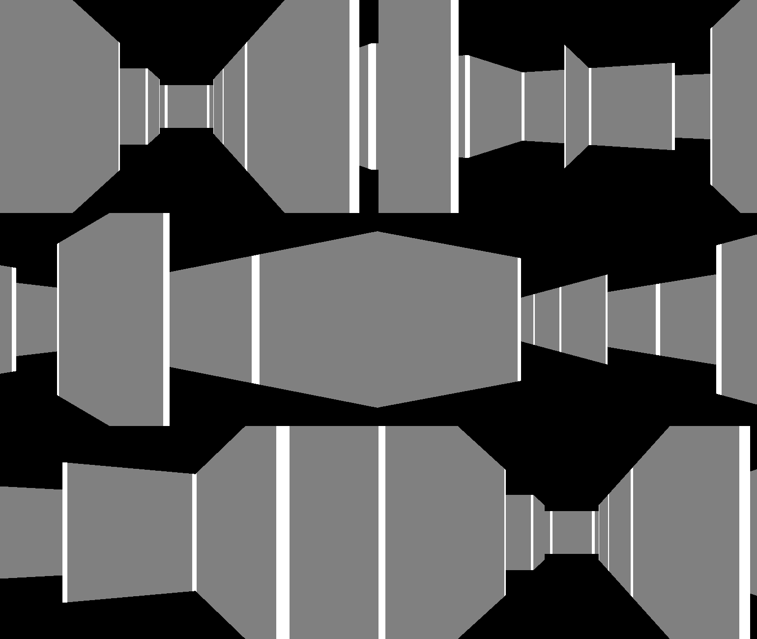
Animated loop of a 360° turn showing the scene rendered with the ray spacing corrected.
The walls are perfectly straight no matter where we stand, and they no longer stretch and squish as the face direction changes. Even with an exaggerated FOV like 140°, things still look bang-on.
TL;DR: To correct squished walls at the edges of the screen, the angular distance between each ray needs to change dynamically based on where it lies within the FOV. The easiest way to accomplish this is to create a projection plane some distance in front of the viewer that functions as a scale model of the screen’s pixel grid, then calculate cast angles that pass through evenly-spaced points on the projection plane.
Extra credit: How come those walls ain’t square?
Congratulations, you endured my screed and fixed your raycaster’s distortion issues. Projection planes are very useful and will serve you well if you find yourself going on to other topics in computer graphics and rendering. In fact, there’s something else that you’re probably facing with your raycaster that can be easily fixed with the projection plane you now have.
Your rendering screen is probably pretty square. It’s strange when you think about it. 4:3 screens have been out of fashion for like twenty years, yet people keep starting new projects at resolutions like 320×200 and 640×480 because… why? What happens if you change the code to make the screen twice as wide as the height? Or vice versa? If your column-drawing code uses the reciprocal of the distance multiplied by the screen height, it probably looks something like these:
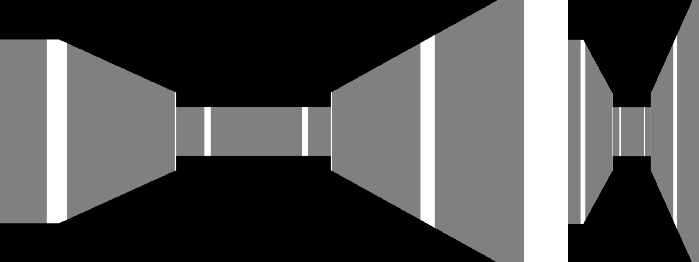
Two views of the same scene. The left view is rendered in a 2:1 aspect ratio and the right view uses 1:2. In each view, the overall shape of the walls is influenced by the shape of the screen that they are rendered onto.
What’s happening here is that the aspect ratio of the screen influences the aspect ratio of the walls. While the screen width is tied to the FOV, and the FOV rigidly defines how much of the world can be seen within that screen width, the wall height has no basis in anything other than whatever the screen height happens to be.
In order to resolve this situation we’ll need another FOV. From this point on I’ll differentiate between the horizontal FOV that we’ve been using up until now and introducing the separate vertical FOV that we’ll need. The horizontal FOV is still set explicitly, but the vertical FOV should be calculated dynamically based on the screen dimensions. As you might be able to surmise after reading the prior sections, we cannot just divide the horizontal FOV by the screen’s aspect ratio—we have to respect the differences between polar and rectangular coordinates. The formula to calculate vertical FOV is:
$$ VFOV = 2 \times \arctan \left( \tan \left({HFOV \over 2}\right) \times {H_{screen} \over W_{screen}} \right) $$The tangent converts the horizontal FOV into a linear slope that can be scaled by the screen’s aspect ratio, and the arctangent converts the scaled slope back to an angle representing the vertical FOV. At each end the angle is divided or multiplied by two so that we only ever work on half of the field, producing a right triangle for the trigonometric functions. Since both FOVs are symmetrical about the face direction, this works fine.
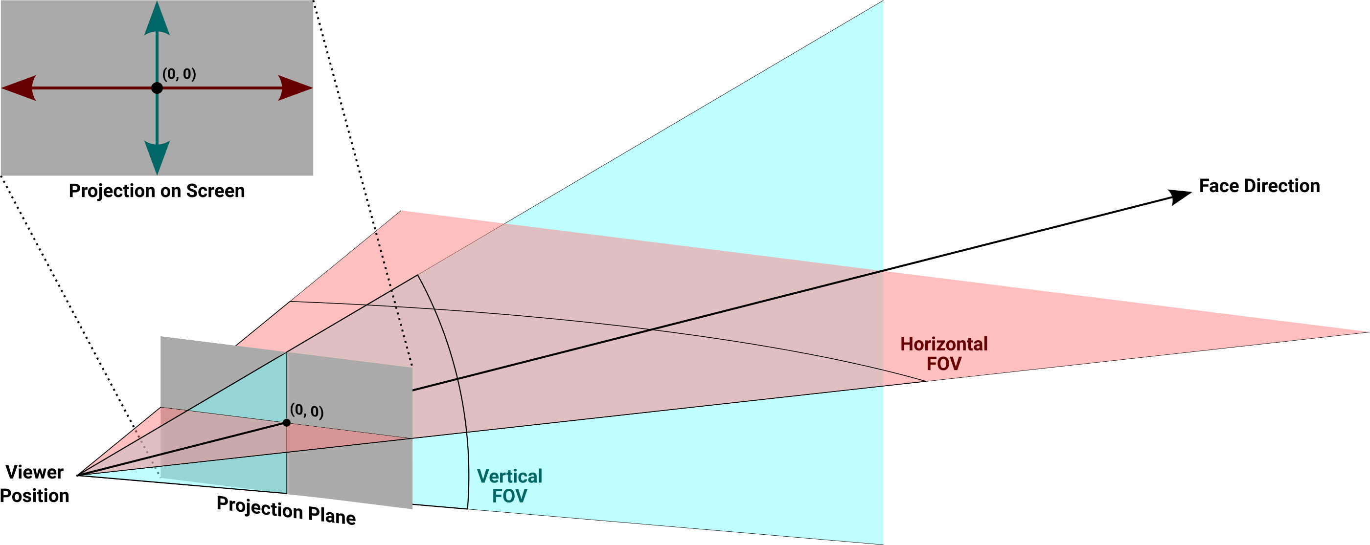
Orthographic view of the horizontal and vertical FOVs passing through the projection plane, and their corresponding location on the screen once rendering is complete.
This is fundamentally the same projection plane we used in the horizontal direction, with the same viewer distance and the same origin centered on the face direction. But since we’re doing vertical operations now, the horizontal width calculations need to be repeated using vertical variables to determine the plane’s height based on the vertical FOV:
$$ {H_{projplane} \over 2} = D_{projplane} \times \tan \left({VFOV \over 2}\right) $$Once the height of the projection plane is known, no further trigonometry is necessary. Everything involved in determining wall height is just linear scaling.
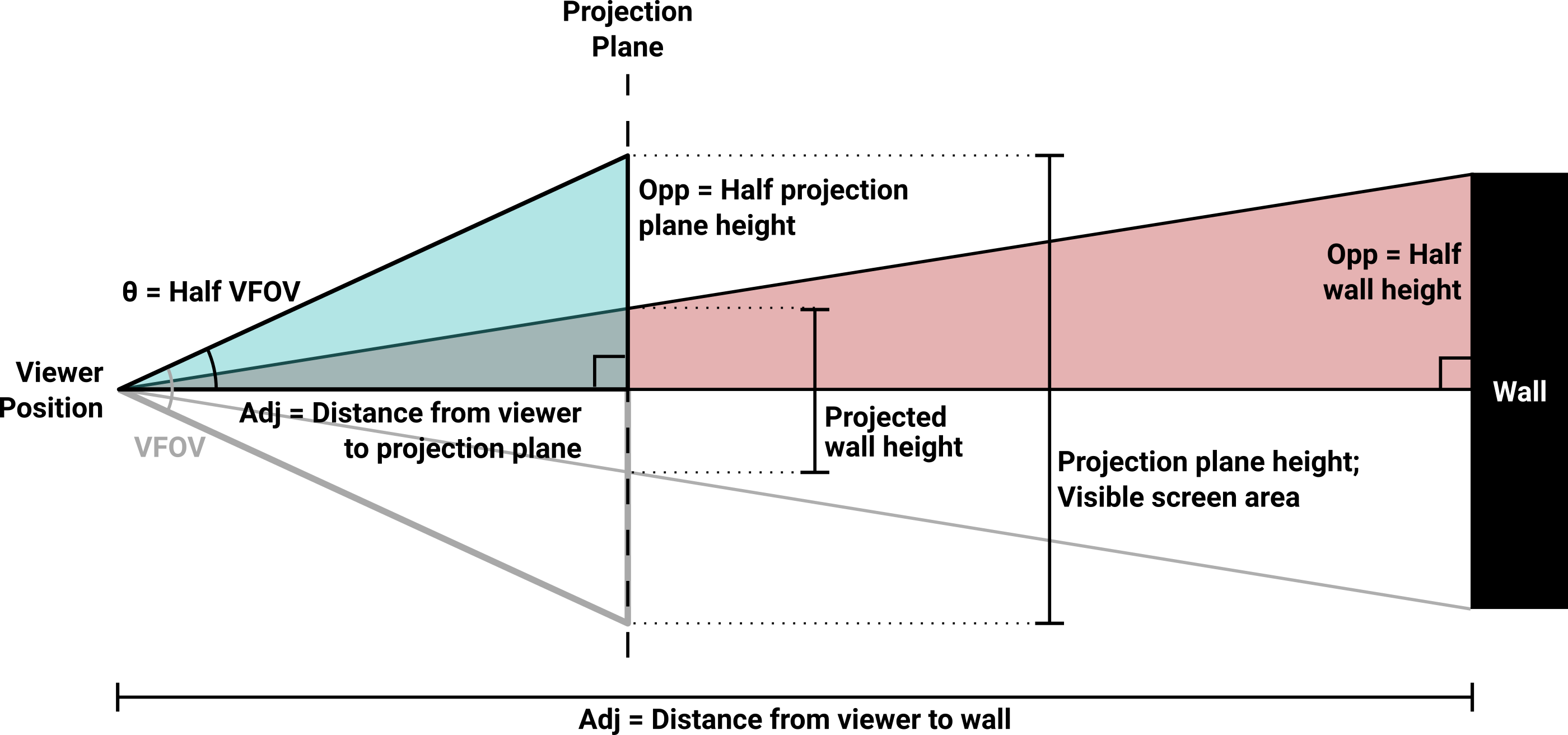
Diagram of the complete wall height projection scheme. The construction of the projection plane and the definition of its height is identical to how it works in the horizontal direction. Half of the wall’s projected height is calculated using half of the projection plane, and the result is doubled before screen display. Note that this view assumes the classic Wolfenstein 3D arrangement where the viewer’s eyeline is vertically centered on the wall at all times.
The only parameter we have left to define is the wall height. That’s completely up to you; there is no golden rule for how it ought to be done. If your aim is for the walls to look like perfect cubes, the height should be set to whatever your map’s grid squares are. In the images accompanying this text, that’s how I chose to do it.
Given the natural wall height $ (H_{wall}) $ and the wall distance calculated during ray travel, the ratio we want is rise-over-run or opposite-over-adjacent—essentially the height of the wall divided by the distance from that wall. This will always be larger than zero, and generally less than one unless the viewer is very close to the wall.
The projected height is found using the ratio between two similar right triangles. Half of the natural wall height $ (H_{halfwall}) $ divided by its distance from the viewer $ (D_{wall}) $ equals the corresponding Y position on the projection plane $ (Y_{projplane}) $ divided by the plane’s distance from the viewer $ (D_{projplane}) $. Remember, only half of the wall’s height is counted, and only half of the projection plane’s vertical area is covered. This is done primarily to keep the vertical calculations similar to the horizontal ones. Feel free to take shortcuts or invent your own ways of optimizing this. Rearranging, we get:
$$ \begin{aligned} H_{halfwall} &= { H_{wall} \over 2 } \\ \\ Y_{projplane} &= D_{projplane} \times {H_{halfwall} \over D_{wall}} \end{aligned} $$With the projected Y value known, all that’s left is to convert this back to a screen pixel: The astute will notice that this equation sort of hand-waves a Y position on the projection plane into a pixel height on the screen. Those are not the same thing, and you and I both know that. Depending on how your texture-mapping code works, it may be easier to receive a height or it may be easier to receive a Y position. In my experience, returning a height is generally more useful since the texturing step is going to need to know that value for scaling.
$$ H_{screenwall} = H_{screen} \times { { Y_{projplane} \times 2 } \over H_{projplane} } $$That should be all there is to it. No matter what the horizontal FOV is set to, or the horizontal/vertical size of the screen, all the walls should be the same shape at all times—the shape you told them to be. This should make things significantly easier when it comes time to support different screen sizes and shapes. This projection plane will also prove extremely useful when it comes time to texture map the floors and ceilings. You are planning to texture map those, aren’t you? And if you should find yourself moving on to more modern techniques like ray tracing, the projection plane mindset will help you greatly there as well.
So, did we fix it?
The scaling and distortion issues discussed in this article are the most common raycasting defects I’ve seen in my travels. They also lead to some of the most repeated online questions, and it seems like all the folks with the answers are either tired of giving them or aren’t equipped to thoroughly explain the problem and its solution.
I wrote this article because I had all of these problems at one point or another. I’d since forgotten the details of the fish eye solution Nobody ever took the time to explain how it worked to me, and at the time I didn’t have the ambition to figure out why it worked on my own. and I had never intentionally built a proper projection plane into a raycaster prior to doing so here. I needed all of this stuff for my own recent project.
Everything I wrote about here was the direct result of me doing something The Wrong Way™ and then having to go back and figure out how to fix it. This was the article that I wish I had found before I wasted so damn much time. I hope that it was useful to you, and best of luck on your raycasting adventure.
« Back to Articles